The anodic oxide film on automobile aluminum alloy parts acts like a layer of armor on their surface. It forms a dense protective layer on the aluminum alloy surface, enhancing the corrosion resistance of the parts and extending their service life. Meanwhile, the oxide film has high hardness, which can improve the wear resistance of the aluminum alloy surface.
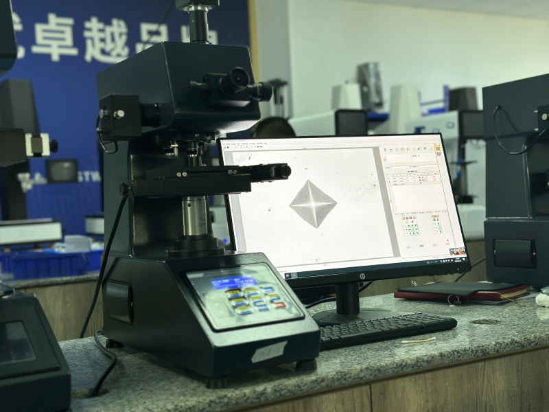
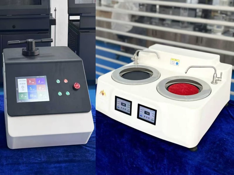
The anodic oxide film of aluminum alloy is characterized by relatively small thickness and relatively high hardness. It is necessary to select testing equipment suitable for micro hardness to avoid damage to the film layer by the indenter. Therefore, we recommend using a micro Vickers hardness tester with a test force of 0.01-1 kgf to test its hardness and thickness. Before the Vickers hardness test, the workpiece to be tested needs to be made into a sample. The equipment required is a metallographic mounting machine (this step can be omitted if the workpiece has two flat surfaces) to mount the workpiece into a sample with two flat surfaces, then use a metallographic grinding and polishing machine to grind and polish the sample until a bright surface is achieved. The mounting machine and grinding & polishing machine are shown in the figure below:
1.Sample Preparation Steps (Applicable for Hardness and Thickness Testing)
1.1 Sampling: Cut a sample of approximately 10mm × 10mm × 5mm from the component to be tested (avoiding the stress concentration area of the component), and ensure the testing surface is the original surface of the oxide film.
1.2 Mounting: Mount the sample with hot mounting material (e.g., epoxy resin), exposing the oxide film surface and cross-section (cross-section is required for thickness testing) to prevent sample deformation during grinding.
1.3 Grinding and Polishing: First, perform step-by-step wet grinding with 400#, 800#, and 1200# sandpapers. Then polish with 1μm and 0.5μm diamond polishing pastes. Finally, ensure the interface between the oxide film and the substrate is scratch-free and clearly visible (the cross-section is used for thickness observation).
2.Testing Method: Vickers Microhardness Method (HV)
2.1 Core Principle:Use a diamond pyramid indenter to apply a small load (usually 50-500g) on the film surface to create an indentation, and calculate the hardness based on the diagonal length of the indentation.
2.2 Key Parameters: The load must match the film thickness (select a load < 100g when the film thickness < 10μm to avoid indentation penetrating to the substrate)
The key is to select a load that matches the film thickness and prevent excessive load from penetrating the oxide film, which would cause the measured results to include the hardness value of the aluminum alloy substrate (the substrate hardness is much lower than that of the oxide film).
If the oxide film thickness is 5-20μm: Select a load of 100-200g (e.g., 100gf, 200gf), and the indentation diameter must be controlled within 1/3 of the film thickness (for example, for a 10μm film thickness, the indentation diagonal ≤ 3.3μm).
If the oxide film thickness is < 5μm (ultra-thin film): Select a load below 50g (e.g., 50gf), and a high-magnification objective lens (40x or higher) must be used to observe the indentation to avoid penetration
When conducting a hardness test, we refer to the standard: ISO 10074:2021 “Specification for Hard Anodic Oxide Coatings on Aluminium and Aluminium Alloys”, which clearly specifies the test forces and hardness ranges to be used when measuring various types of oxide coatings with a micro Vickers hardness tester. The detailed specifications are shown in the table below:
Table:Acceptance values for Vickers microhardness test
|
Alloy |
Microhardness / HV0.05 |
| Class 1 |
400 |
| Class 2(a) |
250 |
| Class 2(b) |
300 |
| Class 3(a) |
250 |
| Class 3(b) | To be agreed upon |
Note: For oxide films with a thickness greater than 50 μm, their microhardness values are relatively low, especially the outer layer of the film
2.3 Precautions:
For the same component, 3 points should be measured in each of 3 different areas, and the average value of the 9 data points should be taken as the final hardness to avoid the impact of local film defects on the results.
If “cracks” or “blurred interfaces” appear at the edge of the indentation, it indicates that the load is too large and has penetrated the film layer. The load should be reduced and the test should be re-conducted.
Post time: Sep-08-2025


